
Liquid turbine flowmeter
LWGY series turbine flow sensor (hereinafter referred to as the sensor) is based on the principle of torque balance and belongs to the speed type flow meter. The sensor has the characteristics of simple structure, light weight, high precision, good repeatability, sensitive response, convenient installation, maintenance and use. It is widely used in petroleum, chemical, metallurgy, water supply, papermaking and other industries. It is an ideal instrument for flow measurement and energy saving.
Key words:
Classification:
Telephone:
E-mail:
Liquid turbine flowmeter
Overview
LWGY series turbine flow sensor (hereinafter referred to as the sensor) is based on the principle of torque balance and belongs to the speed type flow meter. The sensor has the characteristics of simple structure, light weight, high precision, good repeatability, sensitive response, convenient installation, maintenance and use. It is widely used in petroleum, chemical, metallurgy, water supply, papermaking and other industries. It is an ideal instrument for flow measurement and energy saving.
The sensor is used in conjunction with the display instrument. It is suitable for measuring liquids that are not corrosive to stainless steel 1 Cr18Ni9Ti, 2Cr13, corundum Al203 and hard alloy in closed pipelines and have no impurities such as fibers and particles. If it is matched with a display instrument with special functions, it can also carry out quantitative control, excessive alarm, etc. The explosion-proof type (ExmllT6) of this product is selected and can be used in environments with explosion hazards.
The sensor is suitable for the medium whose viscosity is less than 5 × 10⁻⁶m2/s at the working temperature. For the liquid whose viscosity is greater than 5 × 10⁻⁶m2/s, the sensor should be used after the solid liquid calibration. If the user needs to use a special form of sensor, can negotiate the order, need explosion-proof sensor, in the order to explain.
Structural features and working principle
(1) Structural features
The sensor is a hard alloy bearing thrust type, which not only ensures accuracy and improves wear resistance, but also has the characteristics of simple structure, firmness and convenient disassembly and assembly.
(2) Working principle
The fluid flows through the sensor housing. Because the blade of the impeller has a certain angle with the flow direction, the impulse of the fluid makes the blade have a rotating torque. After overcoming the friction torque and fluid resistance, the blade rotates. After the torque is balanced, the rotating speed is stable. Under certain conditions, the rotating speed is proportional to the flow rate. Because the blade has magnetic permeability, it is in the magnetic field of the signal detector (composed of permanent magnetic steel and coil), and rotating blade cutting the rotating blade cutting magnetic field, the magnetic flux of the coil is periodically changed, so that the electric pulse signal is induced at both ends of the coil. This signal is amplified and shaped by the amplifier to form a continuous rectangular pulse wave with a certain amplitude, which can be transmitted to the display instrument to show the fluid Instantaneous flow or total amount. Within a certain flow range, the pulse frequency f is proportional to the instantaneous flow Q of the fluid flowing through the sensor, and the flow equation is:
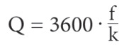
Where:
f-pulse frequency [Hz];
k-instrument coefficient of sensor [1/m3], given by calibration sheet;
Q-instantaneous flow rate of fluid (under working condition)[m/h];
3600 the conversion factor at one second.
The instrument coefficient of each sensor shall be filled in the verification certificate by the manufacturer, and the k value shall be set in the matching display instrument to display the instantaneous flow rate and cumulative total amount.
Basic parameters
Medium temperature:-20~120 ℃. Ambient temperature:-20~65 ℃.
Power supply: voltage: 24VDC, current: ≤ 10mA.
3.6V/0.3mA on battery power. 485 communication current increases by 0.6mA. Transmission distance: the distance from the sensor to the display instrument can reach 1000m.
Selection
|
|
LWGY-□ |
□□□ |
□ |
|
□ |
Description |
|
Type |
LWGY-A |
|
|
|
|
Without field display, output pulse signal |
|
LWGY-B |
Without field display, output 4-20mA standard current signal. |
|||||
|
LWGY-C |
On-site display, dual power supply (lithium battery, 24VDC)485 signal output. |
|||||
|
LWGY-D |
On-site display, dual power supply (lithium battery, 24VDC)4 ~ 20mA two-wire current output |
|||||
|
Nominal diameter |
4 |
4mm |
||||
|
6 |
6mm |
|||||
|
10 |
10mm |
|||||
|
12 |
12mm |
|||||
|
15 |
15mm |
|||||
|
20 |
20mm |
|||||
|
25 |
25mm |
|||||
|
32 |
32mm |
|||||
|
40 |
40mm |
|||||
|
50 |
50mm |
|||||
|
65 |
65mm |
|||||
|
80 |
80mm |
|||||
|
100 |
100mm |
|||||
|
125 |
125mm |
|||||
|
150 |
150mm |
|||||
|
200 |
200mm |
|||||
|
Explosion-proof |
N |
Non-explosion proof type |
||||
|
B |
Explosion-proof type |
|||||
|
Accuracy Class |
5 |
Accuracy 0.5 level |
||||
|
1 |
Accuracy Level 1 |
|||||
|
Turbine Type |
A |
wide range turbine |
||||
|
B |
ordinary turbine |
|||||
Flow range and withstand voltage class
|
Instrument diameter (mm) |
Normal flow range (m³/h) |
Extended Flow Range (m³/h) |
regular connection mode and withstand voltage class |
Special pressure rating (MPa) |
regular pressure tolerance |
|
DN4 |
0.04~0.25 |
0.04~0.4 |
Threaded connection/6.3MPa |
10 16 25 |
0.12MPa |
|
DN6 |
0.1~0.6 |
0.06~0.6 |
Threaded connection/6.3MPa |
4.0 6.0 10 16 25 |
0.08MPa |
|
DN10 |
0.2~1.2 |
0.15~1.5 |
Threaded connection/6.3MPa |
0.05MPa |
|
|
DN15 |
0.6~6 |
0.4~8 |
Threaded connection/6.3MPa |
4.0 6.3 10 16 25 |
0.035MPa |
|
Flange connection/4.0MPa |
|||||
|
DN20 |
0.8~8 |
0.45~9 |
Threaded connection/6.3MPa |
4.0 6.0 10 16 25 |
|
|
Flange connection/4.0MPa |
|||||
|
DN25 |
1~10 |
0.5~10 |
Threaded connection/6.3MPa |
4.0 6.3 10 16 25 |
|
|
Flange connection/4.0MPa |
|||||
|
DN32 |
1.5~15 |
0.8~1.5 |
Threaded connection/6.3MPa |
4.0 6.0 10 16 25 |
0.025MPa |
|
Flange connection/4.0MPa |
|||||
|
DN40 |
2~20 |
1~20 |
Threaded connection/6.3MPa |
4.0 6.3 10 16 25 |
|
|
Flange connection/4.0MPa |
|||||
|
DN50 |
4~40 |
2~40 |
Threaded connection/6.3MPa |
4.0 6.3 10 16 25 |
|
|
Flange connection/4.0MPa |
|||||
|
DN65 |
7~70 |
4~70 |
Threaded connection/1.6MPa |
4.0 6.3 10 16 25 |
|
|
Flange connection/1.6MPa |
|||||
|
DN80 |
10~100 |
5~100 |
Threaded connection/1.6MPa |
4.0 6.3 10 16 25 |
|
|
Flange connection/1.6MPa |
|||||
|
DN100 |
20~200 |
10~200 |
Threaded connection/1.6MPa |
2.5 4.0 6.3 10 16 25 |
|
|
Flange connection/1.6MPa |
|||||
|
DN125 |
25~250 |
13~250 |
Threaded connection/1.6MPa |
4.0 6.3 10 16 25 |
|
|
DN150 |
30~300 |
15~300 |
Threaded connection/1.6MPa |
4.0 6.3 10 16 25 |
|
|
DN200 |
80~800 |
40~800 |
Threaded connection/1.6MPa |
4.0 6.3 10 16 25 |
Overall dimension
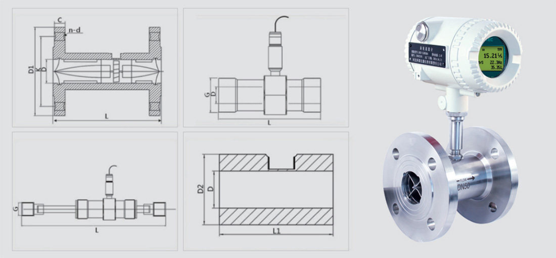
|
Nominal diameter (mm) |
1.6MPa Flange outer diameter D1 |
Flange connection |
Body length L |
Threaded connection English Standard G |
Foreign Sutra D2 |
Length L1 |
|||
|
Center distance K |
aperture d |
number of holes n |
Thickness C |
||||||
|
DN4 |
90 |
60 |
14 |
4 |
14 |
225 |
G1/2 |
|
|
|
DN6 |
90 |
60 |
14 |
4 |
14 |
225 |
G1/2 |
|
|
|
DN8 |
90 |
60 |
14 |
4 |
14 |
345 |
G1/2 |
|
|
|
DN10 |
90 |
60 |
14 |
4 |
14 |
345 |
G1/2 |
|
|
|
DN12 |
95 |
65 |
14 |
4 |
14 |
65 |
G3/4 |
|
|
|
DN15 |
95 |
65 |
14 |
4 |
14 |
75 |
G1 |
36 |
75 |
|
DN20 |
105 |
75 |
14 |
4 |
16 |
85 |
G1 |
44 |
85 |
|
DN25 |
115 |
85 |
14 |
4 |
16 |
100 |
G1 1/4 |
52 |
80 |
|
DN32 |
140 |
100 |
18 |
4 |
18 |
120 |
G1 1/2 |
65 |
90 |
|
DN40 |
150 |
110 |
18 |
4 |
18 |
140 |
G2 |
74 |
90 |
|
DN50 |
165 |
125 |
18 |
4 |
20 |
150 |
G2 1/2 |
93 |
120 |
|
DN65 |
185 |
145 |
18 |
4 |
20 |
175 |
G3 |
106 |
100 |
|
DN80 |
200 |
160 |
18 |
8 |
20 |
200 |
G3 1/2 |
128 |
100 |
|
DN100 |
220 |
180 |
18 |
8 |
22 |
220 |
G4 1/2 |
158 |
100 |
|
DN125 |
250 |
210 |
18 |
8 |
22 |
250 |
|
|
|
|
DN150 |
285 |
240 |
22 |
8 |
24 |
300 |
|
|
|
|
DN200 |
340 |
295 |
22 |
12 |
26 |
360 |
|
|
|
|
DN250 |
405 |
355 |
26 |
12 |
28 |
400 |
|
|
|
|
DN300 |
460 |
410 |
26 |
12 |
32 |
500 |
|
|
|
Flow range and withstand voltage class
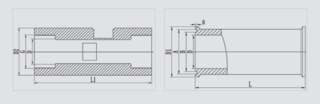
|
Caliber D |
Internal thread |
Clamp connection |
|||||
|
L1(mm) |
D2(mm) |
G(mm) |
L(mm) |
D1(mm) |
A(mm) |
B(mm) |
|
|
DN4 |
80 |
38 |
1/4 |
50 |
50.5 |
46 |
40.5 |
|
DN6 |
80 |
38 |
1/4 |
50 |
50.5 |
46 |
40.5 |
|
DN8 |
80 |
38 |
1/4 |
50 |
50.5 |
46 |
40.5 |
|
DN10 |
80 |
38 |
3/8 |
50 |
50.5 |
46 |
40.5 |
|
DN12 |
80 |
38 |
1/2 |
50 |
50.5 |
46 |
40.5 |
|
DN15 |
110 |
40 |
1/2 |
75 |
50.5 |
46 |
40.5 |
|
DN20 |
133 |
48 |
3/4 |
85 |
50.5 |
46 |
40.5 |
|
DN25 |
150 |
53 |
1 |
100 |
50.5 |
46 |
40.5 |
|
DN32 |
172 |
62 |
11/4 |
120 |
50.5 |
46 |
40.5 |
|
DN40 |
185 |
70 |
11/2 |
140 |
64 |
59 |
53.5 |
|
DN50 |
200 |
78 |
2 |
150 |
78 |
73.5 |
68 |
|
DN65 |
235 |
90 |
21/2 |
175 |
91 |
86 |
80.5 |
|
DN80 |
260 |
100 |
3 |
200 |
106 |
110.5 |
94 |
|
DN100 |
|
|
|
220 |
119 |
113 |
106 |
|
DN125 |
|
|
|
|
|
|
|
|
DN150 |
|
|
|
|
|
|
|
|
DN200 |
|
|
|
|
|
|
|
|
DN250 |
|
|
|
|
|
|
|
|
DN300 |
|
|
|
|
|
|
|
Factory display

Plant display 7

Plant display 8

Plant display 6

Plant display 5

Plant Display 4

Plant Display 9

Plant Exhibition 3

Plant display 2

Factory display
Honor Show

Exhibition style
Previous Page
Next Page
Previous Page
Vortex precession flowmeter
Next Page
Related Products


Product Consulting
We will contact you within one working day. Please pay attention to your email.

Hebei Province. It is a high-tech company mainly engaged in the research and development, manufacturing, sales and service of flow, pressure, temperature, liquid level, and secondary instruments.
Product Series
Contact Us
No.7, South Side of 307, Economic Development Zone, Wuqiang County, Hengshui City, Hebei Province