
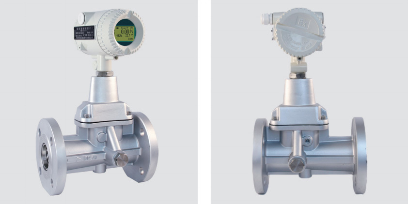
Vortex precession flowmeter
Intelligent vortex precession flowmeter is a new type of gas flow meter developed by our company. The flow meter integrates flow, temperature and pressure detection functions, and can automatically compensate temperature, pressure and compression factor. It is an ideal instrument for gas measurement in petroleum, chemical, electric power, metallurgy and other industries.
Key words:
Classification:
Telephone:
E-mail:
Vortex precession flowmeter
Overview
Intelligent vortex precession flowmeter is a new type of gas flow meter developed by our company. The flow meter integrates flow, temperature and pressure detection functions, and can automatically compensate temperature, pressure and compression factor. It is an ideal instrument for gas measurement in petroleum, chemical, electric power, metallurgy and other industries.
Product Features
1. No mechanical moving parts, not easy to corrosion, stable and reliable, long life, long-term operation without special maintenance;
2. Using 16-bit computer chip, high integration, small size, good performance and strong function of the whole machine;
3. The intelligent flowmeter integrates flow probes, microprocessors, pressure and temperature sensors, and adopts a built-in combination to make the structure more compact. It can directly measure the flow, pressure and temperature of the fluid, and automatically track and compensate and compress in real time Factor correction;
4. The use of dual detection technology can effectively improve the detection signal strength and suppress the interference caused by pipeline vibration;
5. The use of domestic advanced intelligent seismic technology, effectively suppress the vibration and pressure fluctuations caused by the interference signal;
6. The use of Chinese character dot matrix display, display more digits, intuitive and convenient reading, can directly display the volume flow under the working state, the volume flow under the standard state, the total amount, and the medium pressure, temperature and other parameters;
7. Using EEPROM technology, convenient parameter setting, can be permanently saved, and can save up to one year of historical data;
8. The converter can output frequency pulse, 4 ~ 20mA analog signal, and has RS485 interface, can be directly connected with the microcomputer, the transmission distance can reach 1.2km;
9. Multiple physical parameter alarm output, one of which can be selected by the user;
10. The meter head of the flowmeter can rotate 360 degrees, which is simple and convenient to install and use;
11. The pressure and temperature signals are sensor input mode with strong interchangeability;
12. The whole machine has low power consumption and can be powered by internal battery or external power supply.
Main use
Intelligent precession vortex flowmeter can be widely used in petroleum, chemical, electric power, metallurgy, urban gas supply and other industries to measure various gas flows. It is a characteristic product of oil field and urban natural gas transmission and distribution metering and trade metering.
structure and working principle
Flowmeter structure
The flowmeter consists of the following seven basic components (Figure 1):
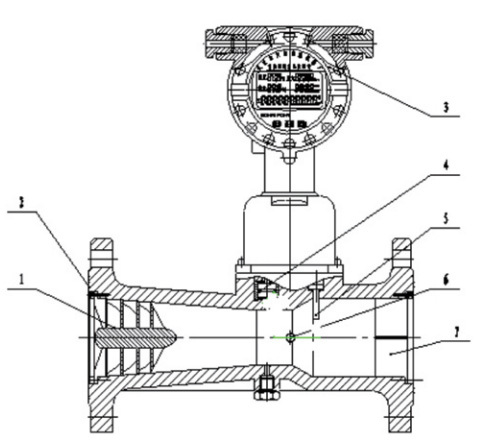
1. Vortex generator
Made of aluminum alloy, a spiral blade with a certain angle is fixed in the front of the shrinking section of the shell to force the fluid to produce a strong vortex flow.
2. Shell
It has a flange and a fluid channel with a certain shape. According to different working pressures, the shell material can be cast aluminum alloy or stainless steel.
3. Intelligent flow meter totalitator (see Figure 3 for the principle)
It is composed of temperature and pressure detection analog channels, flow detection digital channels, micro-processing units, liquid crystal drive circuits and other auxiliary circuits, and is equipped with external signal interface.
4. Temperature sensor
Pt100 platinum resistance for temperature sensitive components, in a certain temperature range, the resistance value and temperature into a corresponding relationship.
5. Pressure sensor
The piezoresistive diffusion silicon bridge is used as a sensitive element, and its bridge arm resistance will be expected to change under the action of external pressure. Therefore, under the action of a certain excitation current, the potential difference between its two output terminals is proportional to the external pressure.
6. Piezoelectric crystal sensor
Installed in the throat near the shell expansion section, the frequency signal of vortex precession can be detected.
7. Racemizer
It is fixed in the outlet section of the housing, and its function is to eliminate the vortex flow to reduce the impact on the performance of the downstream instrument.
Working principle
The flow profile of the flow sensor is similar to the Venturi profile (Figure 2). A set of spiral guide vanes is placed on the inlet side. When the fluid enters the flow sensor, the guide vanes force the fluid to generate a violent vortex flow. When the fluid enters the diffusion section, the vortex flow is affected by the reflux and begins to rotate twice, forming a gyro-type vortex precession phenomenon. The precession frequency is proportional to the flow rate and is not affected by the physical properties and density of the fluid. The precession frequency measured by the detection element can obtain good linearity in a wide flow range. The signal is converted into a pulse signal proportional to the flow rate by the preamplifier, filtering and shaping, and then sent to the microprocessor for integrated processing together with the temperature, pressure and other detection signals. Finally, the measurement results (instantaneous flow, cumulative flow, temperature and pressure data) are displayed on the LCD screen.
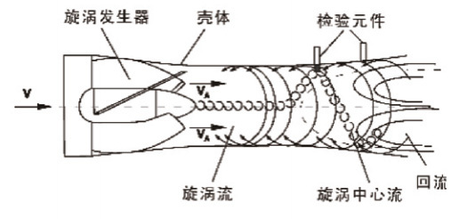
Figure 2
Main technical parameters and functions
Flowmeter specifications, basic parameters and performance indicators
|
Model |
Nominal diameter DN (Mm) |
Flow range (m³/h) |
Nominal pressure (MPa) |
Pressure loss (kPa) |
Shell material |
Accuracy |
|
LUZX-015 |
15 |
0.8~12 |
1.6 |
△P= P/ 1.205 × PN |
stainless steel casting 1Cr18Ni9Ti or cast aluminum alloy shell |
1.5 |
|
LUZX-020 |
20 |
1.5~15 |
2.5 |
|||
|
LUZX-025 |
25 |
2.-30 |
||||
|
LUZX-032 |
32 |
4~60 |
4.0 |
|||
|
LUZX-040 |
40 |
5~70 |
||||
|
LUZX-050 |
50 |
7~130 |
6.3 |
|||
|
LUZX-065 |
65 |
16~200 |
||||
|
LUZX-080 |
80 |
20~300 |
||||
|
LUZX-100 |
100 |
50~800 |
1.6 |
Cast aluminum alloy shell |
||
|
LUZX-125 |
125 |
60~1000 |
||||
|
LUZX-150 |
150 |
120~2000 |
||||
|
LUZX-200 |
200 |
300~3600 |
||||
|
Note: 1. Accuracy: the system accuracy after temperature and pressure correction; 3.2 standard condition: P = 101.325KPa,T = 293.15K 3.3 conditions of use: ambient temperature:-30 ℃ ~ +65 ℃; relative humidity: 5% ~ 95%; medium temperature:-20 ℃ ~ +80 ℃; atmospheric pressure: 86KPa ~ 106KPa |
||||||
Electrical performance index
Working power supply:
A. external power supply: + 24VDC 15%, ripple <5%, suitable for 4 ~ 20mA output, pulse output, alarm output, RS-485, etc;
B. Internal power supply: 1 set of 3.6V lithium batteries (ER26500), when the voltage is lower than 3.0V, an undervoltage indication appears.
Power consumption of the whole machine:
A. External power:<2W;
B. internal power supply: average power consumption 1mW, can be used continuously for more than two years.
Pulse output mode:
A. working condition pulse signal, directly amplify and output the working condition pulse signal detected by the flow sensor through optocoupler isolation, with high level ≥ 20V and low level ≤ 1V;
B. calibration pulse signal, matched with IC card valve controller, high level amplitude ≥ 2.8V, low level amplitude ≤ 0.2V, unit pulse representative volume can be set in the range of 0.001m3~100 m3. When selecting this value, attention must be paid to: the frequency of the calibration pulse signal should be ≤ 900Hz;
C. calibration pulse signal, amplified by optocoupler isolation output, high level ≥ 20V, low level ≤ 1V.
RS-485 communication (photoelectric isolation) can realize the following functions: using RS-485 interface, it can be directly connected to the upper computer or secondary meter, and the temperature and pressure of the medium, and the standard volume flow rate and total standard volume after temperature and pressure compensation can be remote-transmitted; The 4 ~ 20mA standard current signal (photoelectric isolation) is proportional to the standard volume flow rate, and 4mA corresponds to 0 m/h, 20mA corresponds to the maximum standard volume flow (this value can be set in the first-level menu). The system: two-wire system or three-wire system. The flowmeter can automatically identify according to the inserted current module and output correctly.
Control signal output:
A. lower limit alarm signal (LP): photoelectric isolation, high and low level alarm, alarm level can be set, working voltage 12V ~ 24V, maximum load current 50mA;
B. upper limit alarm signal (UP): photoelectric isolation, high and low level alarm, alarm level can be set, working voltage 12V ~ 24V, maximum load current 50mA;
C. valve closing alarm output (BC terminal, for IC card controller): logic gate circuit output, normal output low level, amplitude ≤ 0.2V; Alarm output high level, amplitude ≥ 2.8V, load resistance ≥ 100kΩ;
D. battery undervoltage alarm output (BL terminal, for IC card controller): logic gate circuit output, normal output low level, amplitude ≤ 0.2V; Alarm output high level, amplitude ≥ 2.8V, load resistance ≥ 100kΩ;
Selection and installation
Flow meter selection
In the selection process, two principles should be grasped, namely: first, to ensure production safety, and second, to ensure the accuracy of use. To this end, three selection parameters must be implemented, namely, the maximum, minimum and common flow in the near and long term (mainly used to select the nominal diameter of the instrument), the design pressure of the measured medium (mainly used to select the nominal pressure level of the instrument), and the actual working pressure (mainly used to select the pressure level of the instrument pressure sensor).
a. When the measured flow is known to be the volume flow under working conditions, the adapted nominal diameter can be directly selected according to the flow range in the table;
B. When it is known that the measured flow is the volume flow under standard conditions, the standard volume flow QN shall be converted to the volume flow Qv under working conditions, and then the corresponding nominal diameter shall be selected according to the flow range in the technical parameter table;
C. when the two caliber flow meters can cover the lowest and highest volume flow, the pressure loss allows, should try to choose a small caliber;
d. Do not make the actual minimum flow Qmin lower than the lower flow limit of the selected nominal diameter flowmeter;
E. flow range, nominal pressure when there are special requirements can be ordered by agreement.
The selection calculation formula is as follows:
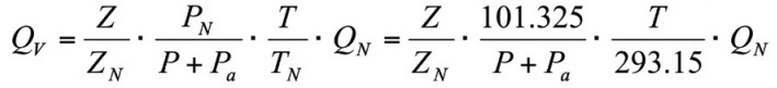
In the formula: T, P and Pa have the same meanings as above, Q is the volume flow rate, Qn is the standard volume flow rate, and Z/Zn values are listed in Table 2. Due to the large calculation step, the data in the table are for reference only. The data in the table are calculated according to the real relative density Gr = 0.600 of natural gas, and the mole fractions of nitrogen and carbon dioxide are 0.00. When the medium pressure is lower than 0.1MPa, it can be estimated by Z/Zn = 1.
|
Zg temperature ℃ → Zn absolute pressure (MPa)↓ |
-20 |
-15 |
-10 |
-5 |
0 |
5 |
10 |
15 |
20 |
25 |
|
0.10 |
1.0000 |
1.0000 |
1.0000 |
1.0000 |
1.0000 |
1.0000 |
1.0000 |
1.0000 |
1.0000 |
1.0000 |
|
0.20 |
1.0034 |
1.0032 |
1.0030 |
1.0029 |
1.0027 |
1.0025 |
1.0024 |
1.0023 |
1.0021 |
1.0020 |
|
0.30 |
1.0069 |
1.0065 |
1.0061 |
1.0058 |
1.0055 |
1.0051 |
1.0048 |
1.0046 |
1.0043 |
1.0041 |
|
0.40 |
1.0104 |
1.0098 |
1.0093 |
1.0087 |
1.0082 |
1.0078 |
1.0073 |
1.0069 |
1.0065 |
1.0061 |
|
0.50 |
1.0140 |
1.0132 |
1.0124 |
1.0117 |
1.0110 |
1.0104 |
1.0098 |
1.0092 |
1.0087 |
1.0082 |
|
1.00 |
1.0325 |
1.0305 |
1.0286 |
1.0269 |
1.0253 |
1.0238 |
1.0223 |
1.0210 |
1.0198 |
1.0186 |
|
1.50 |
1.0518 |
1.0485 |
1.0455 |
1.0426 |
1.0400 |
1.0375 |
1.0352 |
1.0331 |
1.0311 |
1.0293 |
|
2.00 |
1.0722 |
1.0674 |
1.0630 |
1.0589 |
1.0551 |
1.0516 |
1.0484 |
1.0454 |
1.0426 |
1.0400 |
|
2.50 |
1.0936 |
1.0872 |
1.0812 |
1.0758 |
1.0708 |
1.0661 |
1.0619 |
1.0580 |
1.0543 |
1.0510 |
|
3.00 |
1.1162 |
1.1078 |
1.1002 |
1.0933 |
1.0869 |
1.0810 |
1.0757 |
1.0707 |
1.0662 |
1.0620 |
|
3.50 |
1.1400 |
1.1295 |
1.1200 |
1.1113 |
1.1035 |
1.0963 |
1.0897 |
1.0837 |
1.0782 |
1.0732 |
|
4.00 |
1.1651 |
1.1521 |
1.1405 |
1.1300 |
1.1205 |
1.1119 |
1.1041 |
1.0969 |
1.0904 |
1.0844 |
|
4.50 |
1.1915 |
1.1758 |
1.1618 |
1.1493 |
1.1380 |
1.1278 |
1.1186 |
1.1103 |
1.1027 |
1.0957 |
|
5.00 |
1.2194 |
1.2005 |
1.1839 |
1.1691 |
1.1559 |
1.1441 |
1.1334 |
1.1238 |
1.1150 |
1.1071 |
|
5.50 |
1.2486 |
1.2262 |
1.2067 |
1.1895 |
1.1742 |
1.1606 |
1.1484 |
1.1374 |
1.1274 |
1.1185 |
|
6.00 |
1.2794 |
1.2530 |
1.2302 |
1.2104 |
1.1928 |
1.1773 |
1.1634 |
1.1510 |
1.1399 |
1.1298 |
|
6.50 |
1.3113 |
1.2806 |
1.2544 |
1.2316 |
1.2117 |
1.1942 |
1.1786 |
1.1647 |
1.1522 |
1.1411 |
|
7.00 |
1.3444 |
1.3091 |
1.2790 |
1.2532 |
1.2308 |
1.2111 |
1.1937 |
1.1783 |
1.1645 |
1.1522 |
|
7.50 |
1.3785 |
1.3381 |
1.3030 |
1.2750 |
1.2499 |
1.2280 |
1.2088 |
1.1918 |
1.1767 |
1.1632 |
|
8.00 |
1.4131 |
1.3673 |
1.3291 |
1.2967 |
1.2689 |
1.2448 |
1.2237 |
1.2051 |
1.1886 |
1.1740 |
|
Zg temperature ℃ → Zn absolute pressure (MPa)↓ |
30 |
35 |
40 |
45 |
50 |
55 |
60 |
65 |
70 |
75 |
|
0.10 |
1.0000 |
1.0000 |
1.0000 |
1.0000 |
1.0000 |
1.0000 |
1.0000 |
1.0000 |
1.0000 |
1.0000 |
|
0.20 |
1.0019 |
1.0018 |
1.0017 |
1.0016 |
1.0015 |
1.0014 |
1.0013 |
1.0012 |
1.0012 |
1.0011 |
|
0.30 |
1.0038 |
1.0036 |
1.0034 |
1.0032 |
1.0030 |
1.0029 |
1.0027 |
1.0025 |
1.0024 |
1.0023 |
|
0.40 |
1.0058 |
1.0054 |
1.0051 |
1.0048 |
1.0046 |
1.0043 |
1.0041 |
1.0038 |
1.0036 |
1.0034 |
|
0.50 |
1.0077 |
1.0073 |
1.0069 |
1.0065 |
1.0061 |
1.0058 |
1.0055 |
1.0052 |
1.0049 |
1.0046 |
|
1.00 |
1.0176 |
1.0166 |
1.0156 |
1.0147 |
1.0139 |
1.0131 |
1.0124 |
1.0117 |
1.0110 |
1.0104 |
|
1.50 |
1.0275 |
1.0259 |
1.0244 |
1.0230 |
1.0217 |
1.0204 |
1.0193 |
1.0182 |
1.0171 |
1.0162 |
|
2.00 |
1.0376 |
1.0354 |
1.0333 |
1.0313 |
1.0295 |
1.0277 |
1.0261 |
1.0246 |
1.0232 |
1.0214 |
|
2.50 |
1.0478 |
1.0449 |
1.0422 |
1.0396 |
1.0372 |
1.0350 |
1.0329 |
1.0310 |
1.0292 |
1.0274 |
|
3.00 |
1.0581 |
1.0545 |
1.0511 |
1.0480 |
1.0450 |
1.0423 |
1.0397 |
1.0373 |
1.0351 |
1.0330 |
|
3.50 |
1.0685 |
1.0641 |
1.0600 |
1.0563 |
1.0528 |
1.0495 |
1.0464 |
1.0436 |
1.0409 |
1.0384 |
|
4.00 |
1.0789 |
1.0737 |
1.0690 |
1.0646 |
1.0605 |
1.0567 |
1.0531 |
1.0498 |
1.0467 |
1.0438 |
|
4.50 |
1.0894 |
1.0834 |
1.0779 |
1.0728 |
1.0681 |
1.0638 |
1.0597 |
1.0558 |
1.0523 |
1.0490 |
|
5.00 |
1.0998 |
1.0930 |
1.0868 |
1.0811 |
1.0757 |
1.0708 |
1.0662 |
1.0619 |
1.0579 |
1.0542 |
|
5.50 |
1.1103 |
1.1026 |
1.0956 |
1.0892 |
1.0832 |
1.0777 |
1.0726 |
1.0678 |
1.0633 |
1.0592 |
|
6.00 |
1.1207 |
1.1122 |
1.1044 |
1.0972 |
1.0906 |
1.0845 |
1.0788 |
1.0736 |
1.0687 |
1.0641 |
|
6.50 |
1.1310 |
1.1216 |
1.1130 |
1.1051 |
1.0979 |
1.0912 |
1.0850 |
1.0729 |
1.0738 |
1.0689 |
|
7.00 |
1.1411 |
1.1309 |
1.1215 |
1.1129 |
1.1050 |
1.0977 |
1.0910 |
1.0847 |
1.0789 |
1.0735 |
|
7.50 |
1.1511 |
1.1400 |
1.1298 |
1.1205 |
1.1120 |
1.1041 |
1.0968 |
1.0900 |
1.0838 |
1.0780 |
|
8.00 |
1.1609 |
1.1489 |
1.1380 |
1.1297 |
1.1187 |
1.1103 |
1.1024 |
1.0952 |
1.0885 |
1.0823 |
Factory display

Plant display 7

Plant display 8

Plant display 6

Plant display 5

Plant Display 4

Plant Display 9

Plant Exhibition 3

Plant display 2

Factory display
Honor Show

Exhibition style
Previous Page
Next Page
Previous Page
None
Next Page
Related Products


Product Consulting
We will contact you within one working day. Please pay attention to your email.

Hebei Province. It is a high-tech company mainly engaged in the research and development, manufacturing, sales and service of flow, pressure, temperature, liquid level, and secondary instruments.
Product Series
Contact Us
No.7, South Side of 307, Economic Development Zone, Wuqiang County, Hengshui City, Hebei Province