
LWGY-W Clamp-Type Liquid Turbine Flowmeter
Our company’s clamp-type liquid turbine flowmeter features a quick-release clamp connection, making it easy to disassemble, assemble, and clean, and it meets hygienic standards. Based on the principle of turbine rotation, it offers high measurement accuracy and rapid response, making it ideal for measuring the flow of clean liquids in industries such as food, pharmaceuticals, and beverages. It is stable, reliable, and easy to maintain.
Key words:
Classification:
Telephone:
E-mail:
LWGY-W Clamp-Type Liquid Turbine Flowmeter
Overview
The LWGY series turbine flow sensor (hereinafter referred to as the sensor) is a velocity-type flow meter based on the principle of torque balance. The sensor features a simple structure, lightweight design, high accuracy, excellent repeatability, rapid response, and ease of installation, maintenance, and use. It is widely used in industries such as petroleum, chemical engineering, metallurgy, water supply, and papermaking, making it an ideal instrument for flow measurement and energy conservation.
The sensor is designed for use with display instruments and is suitable for measuring liquids in closed pipelines that do not corrode stainless steel grades 1Cr18Ni9Ti and 2Cr13, as well as alumina (Al2O3) and cemented carbides, provided the liquids are free of fibers, particles, and other impurities. When paired with display instruments equipped with special functions, this sensor can also perform quantitative control and over-limit alarms. The explosion-proof version (ExmllT6) of this product is available for use in environments with potential explosion hazards.
The sensor is suitable for media with a viscosity of less than 5×10⁻⁶ m²/s at the operating temperature. For liquids with a viscosity greater than 5×10⁻⁶ m²/s, the sensor must be calibrated using actual liquid samples before use. If users require sensors in special configurations, they may negotiate and place orders accordingly. When ordering explosion-proof sensors, please specify this requirement in the order.
Structural Features and Working Principle
(1) Structural Features
The sensor features a thrust-type design with cemented carbide bearings, which not only ensures high precision and enhanced wear resistance but also boasts a simple, robust structure that is easy to assemble and disassemble.
(2) Operating Principle
As the fluid flows through the sensor housing, the blades of the impeller, which are angled relative to the flow direction, experience a force exerted by the fluid. This force generates a torque that causes the blades to rotate. After overcoming the frictional torque and fluid resistance, the blades begin to spin steadily once the torque reaches equilibrium. Under certain conditions, the rotational speed is directly proportional to the fluid velocity. Since the blades are ferromagnetic, they enter the magnetic field generated by a signal detector—comprising a permanent magnet and a coil. As the rotating blades cut across the magnetic field lines, they periodically alter the magnetic flux passing through the coil, thereby inducing electrical pulse signals at the coil’s terminals. These signals are then amplified and shaped by an amplifier to produce continuous rectangular pulses of a specific amplitude, which can be transmitted over long distances to display instruments, allowing them to indicate either the instantaneous flow rate or the total accumulated flow of the fluid. Within a certain flow range, the pulse frequency f is directly proportional to the instantaneous flow rate Q of the fluid passing through the sensor; the flow equation is:

In the formula:
f: Pulse frequency [Hz];
k— The meter coefficient of the sensor [1/m³], provided by the calibration certificate;
Q— Instantaneous flow rate of the fluid (in operating condition) [m³/h];
Conversion factor for 3600 seconds.
The meter coefficient for each sensor is filled in the calibration certificate by the manufacturer. After the k-value is entered into the corresponding display instrument, it can display both the instantaneous flow rate and the cumulative total.
Basic Parameters
Medium temperature: -20~+120℃. Ambient temperature: -20~+65℃.
Power supply: Voltage: 24VDC, Current: ≤10mA.
When powered by batteries, the current consumption is 3.6V/0.3mA. The 485 communication current increases by 0.6mA. Transmission distance: The distance between the sensor and the display instrument can reach up to 1000m.
Selection
|
LWGY- □ |
□□□ |
□ |
|
□ |
Instructions |
Type |
LWGY-A |
|
|
|
|
No on-site display; outputs pulse signals. |
LWGY-B |
Without on-site display, it outputs a standard 4-20mA current signal. | |||||
LWGY-C |
The on-site display shows dual-power supply (lithium battery, 24VDC) with 485 signal output. | |||||
LWGY-D |
The on-site display shows a dual-power supply (lithium battery, 24VDC) with a 4–20mA two-wire current output. | |||||
Nominal diameter |
4 |
4mm | ||||
6 |
6mm | |||||
10 |
10mm | |||||
12 |
12mm | |||||
15 |
15mm | |||||
20 |
20mm | |||||
25 |
25mm | |||||
32 |
32mm | |||||
40 |
40mm | |||||
50 |
50mm | |||||
65 |
65mm | |||||
80 |
80mm | |||||
100 |
100mm | |||||
125 |
125mm | |||||
150 |
150mm | |||||
200 |
200mm | |||||
Explosion-proof |
N |
Non-explosion-proof | ||||
B |
Explosion-proof | |||||
Accuracy class |
5 |
Accuracy class 0.5 | ||||
1 |
Accuracy Class 1 | |||||
Turbine type |
A |
Wide-range turbine | ||||
B |
Standard turbine | |||||
Flow range and pressure rating
Instrument diameter (mm) |
Normal flow range (m³/h) |
Expand the traffic range (m³/h) |
Conventional connection method With withstanding voltage rating |
Specially designed pressure rating (MPa) |
Regular tolerance pressure |
DN4 |
0.04–0.25 |
0.04–0.4 |
Threaded connection / 6.3 MPa |
10 16 25 | 0.12MPa |
DN6 |
0.1–0.6 |
0.06–0.6 |
Threaded connection / 6.3 MPa |
4.0 6.0 10 16 25 | 0.08MPa |
DN10 |
0.2–1.2 |
0.15–1.5 |
Threaded connection / 6.3 MPa |
0.05MPa |
|
DN15 |
0.6–6 |
0.4–8 |
Threaded connection / 6.3 MPa |
4.0 6.3 10 16 25 |
0.035MPa |
Flange connection / 4.0 MPa |
|||||
DN20 |
0.8 to 8 |
0.45–9 |
Threaded connection / 6.3 MPa |
4.0 6.0 10 16 25 | |
Flange connection / 4.0 MPa |
|||||
DN25 |
1 to 10 |
0.5–10 |
Threaded connection / 6.3 MPa |
4.0 6.3 10 16 25 | |
Flange connection / 4.0 MPa |
|||||
DN32 |
1.5 to 15 |
0.8–1.5 |
Threaded connection / 6.3 MPa |
4.0 6.0 10 16 25 | 0.025MPa |
Flange connection / 4.0 MPa |
|||||
DN40 |
2 to 20 |
1 to 20 |
Threaded connection / 6.3 MPa |
4.0 6.3 10 16 25 | |
Flange connection / 4.0 MPa |
|||||
DN50 |
4 to 40 |
2 to 40 |
Threaded connection / 6.3 MPa |
4.0 6.3 10 16 25 | |
Flange connection / 4.0 MPa |
|||||
DN65 |
7 to 70 |
4 to 70 |
Threaded connection / 1.6 MPa |
4.0 6.3 10 16 25 | |
Flange connection / 1.6 MPa |
|||||
DN80 |
10 to 100 |
5–100 |
Threaded connection / 1.6 MPa |
4.0 6.3 10 16 25 | |
Flange connection / 1.6 MPa |
|||||
DN100 |
20 to 200 |
10–200 |
Threaded connection / 1.6 MPa |
2.5 4.0 6.3 10 16 25 | |
Flange connection / 1.6 MPa |
|||||
DN125 |
25–250 |
13–250 |
Threaded connection / 1.6 MPa |
4.0 6.3 10 16 25 | |
DN150 |
30–300 |
15–300 |
Threaded connection / 1.6 MPa |
4.0 6.3 10 16 25 | |
DN200 |
80–800 |
40–800 |
Threaded connection / 1.6 MPa |
4.0 6.3 10 16 25 |
External dimensions
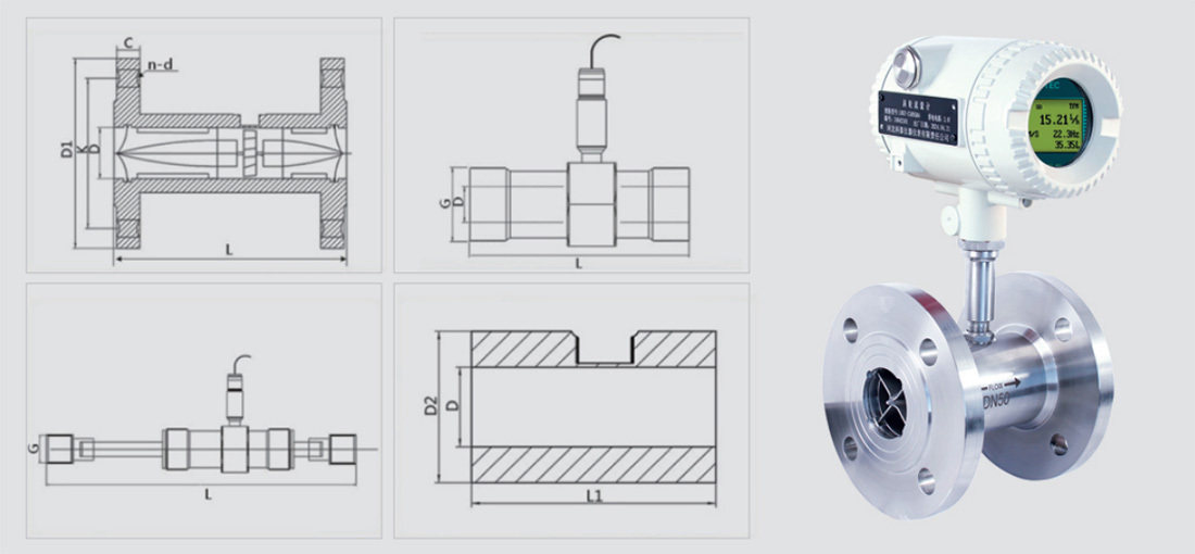
Nominal diameter (mm) |
1.6MPa Flange outer diameter D1 |
Flange connection |
Body length L |
Threaded connection British Standard G |
Foreign Economy D2 |
Length L1 |
|||
Center distance K |
Aperture d |
Number of holes n |
Thickness C |
||||||
DN4 |
90 |
60 |
14 |
4 |
14 |
225 |
G1/2 |
|
|
DN6 |
90 |
60 |
14 |
4 |
14 |
225 |
G1/2 |
|
|
DN8 |
90 |
60 |
14 |
4 |
14 |
345 |
G1/2 |
|
|
DN10 |
90 |
60 |
14 |
4 |
14 |
345 |
G1/2 |
|
|
DN12 |
95 |
65 |
14 |
4 |
14 |
65 |
G3/4 |
|
|
DN15 |
95 |
65 |
14 |
4 |
14 |
75 |
G1 | 36 |
75 |
DN20 |
105 |
75 |
14 |
4 |
16 |
85 |
G1 | 44 |
85 |
DN25 |
115 |
85 |
14 |
4 |
16 |
100 |
G1 1/4 | 52 |
80 |
DN32 |
140 |
100 |
18 |
4 |
18 |
120 |
G1 1/2 | 65 |
90 |
DN40 |
150 |
110 |
18 |
4 |
18 |
140 |
G2 | 74 |
90 |
DN50 |
165 |
125 |
18 |
4 |
20 |
150 |
G2 1/2 | 93 |
120 |
DN65 |
185 |
145 |
18 |
4 |
20 |
175 |
G3 | 106 |
100 |
DN80 |
200 |
160 |
18 |
8 |
20 |
200 |
G3 1/2 | 128 |
100 |
DN100 |
220 |
180 |
18 |
8 |
22 |
220 |
G4 1/2 | 158 |
100 |
DN125 |
250 |
210 |
18 |
8 |
22 |
250 |
|
|
|
DN150 |
285 |
240 |
22 |
8 |
24 |
300 |
|
|
|
DN200 |
340 |
295 |
22 |
12 |
26 |
360 |
|
|
|
DN250 |
405 |
355 |
26 |
12 |
28 |
400 |
|
|
|
DN300 |
460 |
410 |
26 |
12 |
32 |
500 |
|
|
|
Flow range and pressure rating
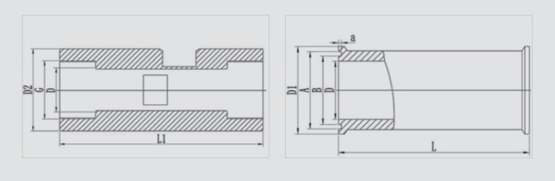
Caliber D |
Internal thread |
Clamp connection |
|||||
L1 (mm) |
D2(mm) |
G(mm) |
L(mm) |
D1 (mm) |
A(mm) |
B(mm) |
|
DN4 |
80 |
38 |
1/4 |
50 |
50.5 |
46 |
40.5 |
DN6 |
80 |
38 |
1/4 |
50 |
50.5 |
46 |
40.5 |
DN8 |
80 |
38 |
1/4 |
50 |
50.5 |
46 |
40.5 |
DN10 |
80 |
38 |
3/8 |
50 |
50.5 |
46 |
40.5 |
DN12 |
80 |
38 |
1/2 |
50 |
50.5 |
46 |
40.5 |
DN15 |
110 |
40 |
1/2 |
75 |
50.5 |
46 |
40.5 |
DN20 |
133 |
48 |
3/4 |
85 |
50.5 |
46 |
40.5 |
DN25 |
150 |
53 |
1 |
100 |
50.5 |
46 |
40.5 |
DN32 |
172 |
62 |
November 4 |
120 |
50.5 |
46 |
40.5 |
DN40 |
185 |
70 |
11/2 |
140 |
64 |
59 |
53.5 |
DN50 |
200 |
78 |
2 |
150 |
78 |
73.5 |
68 |
DN65 |
235 |
90 |
21/2 |
175 |
91 |
86 |
80.5 |
DN80 |
260 |
100 |
3 |
200 |
106 |
110.5 |
94 |
DN100 |
|
|
|
220 |
119 |
113 |
106 |
DN125 |
|
|
|
|
|
|
|
DN150 |
|
|
|
|
|
|
|
DN200 |
|
|
|
|
|
|
|
DN250 |
|
|
|
|
|
|
|
DN300 |
|
|
|
|
|
|
|
Factory display

Plant display 7

Plant display 8

Plant display 6

Plant display 5

Plant Display 4

Plant Display 9

Plant Exhibition 3

Plant display 2

Factory display
Honor Show

Exhibition style
Previous Page
Next Page
Previous Page
None
Next Page
Related Products


Product Consulting
We will contact you within one working day. Please pay attention to your email.

Founded in 2014, Hebei Ketai Instrumentation Co., Ltd. is located in Wuqiang County Economic Development Zone, Hengshui City, Hebei Province. It is a high-tech enterprise mainly engaged in the research, development, manufacturing, sales and service of flow, pressure, temperature, liquid level and secondary instrument series.
Product Series
Contact Us
Hotline: +86 16633827910
WhatsApp: +86 18631835127
No.7, South Side of 307, Economic Development Zone, Wuqiang County, Hengshui City, Hebei Province