
LUGB-FW Temperature-Compensated Flow Meter
This temperature-compensated flowmeter features an integrated temperature-sensing module that automatically compensates for measurement deviations caused by changes in the medium’s temperature. Relying on a precise algorithm to correct flow data, it delivers high measurement accuracy and excellent stability. It is well-suited for temperature-sensitive media such as steam and gases, making it ideal for high-precision flow monitoring applications in fields including power generation, metallurgy, and gas transmission.
Key words:
Classification:
Telephone:
E-mail:
LUGB-FW Temperature-Compensated Flow Meter
Overview
The LUGB series vortex flowmeter is a flow measurement instrument that uses a piezoelectric crystal as the sensing element and outputs a standard signal proportional to the flow rate. This instrument can be directly connected to instrumentation devices or used in conjunction with computers and distributed control systems to measure flow parameters of various media. Based on the detection principle of fluid-induced vortices, the piezoelectric crystal used to detect these vortices does not come into contact with the medium itself. As a result, this instrument features a simple structure, excellent versatility, and high stability.
The LUGB series vortex flowmeter can be used for flow measurement and metering of various gases, liquids, and steam. The LUGB series vortex flowmeter can be used in conjunction with the intelligent totalizers manufactured by our company, as well as with smart instruments produced by other instrument manufacturers, giving it highly versatile compatibility.
Working principle
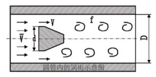
The fundamental principle of the vortex flowmeter is the Karman vortex street principle, which states that “the frequency of vortex shedding is directly proportional to the flow velocity.” The diameter of the flowmeter’s flow passage body is essentially the same as the instrument’s nominal bore size. As shown in Figure 1, a roughly isosceles triangular cylinder is inserted into the flow passage body; the cylinder’s axis is perpendicular to the direction of flow of the medium being measured, with its base facing the fluid.

In the formula:
f: Frequency (Hz) of vortex shedding from the side of a cylindrical body;
V— Lateral flow velocity in the column (m/s); d— Width of the column’s upstream face (m); Sr— Strouhal number.
It is a constant that depends on the cross-sectional shape of the cylinder and is essentially independent of the fluid properties and flow velocity.
Product Features and Applications
1. The sensor measurement probe is encapsulated using a special process, with a standard temperature resistance of 250℃ and a high-temperature version capable of withstanding up to 350℃.
2. The sensitive element is encapsulated within the probe body, and the sensing element does not come into contact with the measured medium, ensuring a long service life.
3. The sensor features a compensation design to enhance the instrument’s seismic resistance.
4. Simple structure with no moving parts, offering high durability;
5. Within the specified Reynolds number range, the measurement is unaffected by the medium’s temperature, pressure, or viscosity.
6. The flowmeter can be used in explosion-proof environments and offers excellent safety performance.
7. Wide measurement range, up to 10:1;
8. Highly versatile, capable of measuring both dirty gases and liquids;
9. This instrument can be widely used for measuring the flow rates of various media—including water supply and drainage in large, medium, and small pipelines, industrial circulation systems, wastewater treatment, oils and chemical reagents, as well as compressed air, saturated and superheated steam, natural gas, and other diverse media.
Technical Parameters
| Nominal Diameter (mm) | 15, 20, 25, 32, 40, 50, 65, 80, 100, 125, 150, 200, 250, 300 |
| Instrument material | 1Cr18Ni9Ti |
| Nominal pressure (MPa) | PN 2.5 MPa; PN 4.0 MPa |
| Measured medium temperature (℃) | 40~+250℃; -40~+350℃ (customization required) |
| Environmental conditions | Temperature: -10 to +55℃, relative humidity: 5% to 90%, atmospheric pressure: 86 to 106 kPa |
| Accuracy class | For liquid measurement: ±1.5% of the indicated value; for gas or steam measurement: ±1.5% of the indicated value. |
| Range ratio | 1:10; 1:15 |
| Resistance loss coefficient | Cd < 2.6 |
| Output signal | Sensor: Pulse frequency signal, 0.1–3000 Hz; low level ≤ 1 V, high level ≥ 6 V. Transmitter: Two-wire 4–20 mA DC current signal |
| Power supply | Voltage pulse type: +24VDC, +12VDC On-site display type: The instrument comes with a built-in 3.6V lithium battery and +24VDC (optional). |
| Signal transmission line | STVPV3×0.3 (three-wire system), 2×0.3 (two-wire system) |
| Transmission distance | ≤500m |
| Signal line interface | Internal thread M20×1.5 |
| Explosion-proof rating | ExdlIBT6 |
| Protection level | IP65 |
| Allow vibration acceleration | 1.0g |
Selection
Product Model and Marking |
Instructions |
|||||||
Model |
LUGB |
|
|
|
Flow sensor utilizing the Karman vortex street principle Flange standard for the table body: GB/T9119.10-2000. The product comes with a card-mounted flange, bolts, and gaskets upon出厂. |
|||
Flange connection |
1 |
|||||||
Flange fitting |
2 |
|||||||
Threaded connection |
3 |
|||||||
Clamp-type |
4 |
|||||||
Measured medium |
Gas liquid vapor |
1 |
||||||
2 3 |
||||||||
Caliber |
01 |
|
15mm | |||||
2 |
20mm | |||||||
02 |
25mm | |||||||
03 |
32mm | |||||||
04 |
40mm | |||||||
05 |
50mm | |||||||
06 |
65mm | |||||||
08 |
80mm | |||||||
10 |
100mm | |||||||
12 |
125mm | |||||||
15 |
150mm | |||||||
20 |
200mm | |||||||
25 |
250mm | |||||||
30 |
300mm | |||||||
|
N |
12/24VDC power supply, no display, pulse output | ||||||
B |
Battery-powered, on-site display, pulse output | |||||||
C |
12/24VDC power supply, on-site display, 4-20mA/pulse output | |||||||
And E |
Battery-powered, on-site display, 485 communication output | |||||||
H |
12/24VDC power supply, on-site display, HART output | |||||||
W |
Temperature compensation | |||||||
Y |
Pressure compensation | |||||||
G |
High-temperature type | |||||||
F |
Split type | |||||||
|
And E |
Explosion-proof, ExdIIBT6 | ||||||
N |
Not explosion-proof | |||||||
Example: To measure steam using a flange-mounted, explosion-proof vortex flowmeter with a pipe diameter of DN50, where the on-site requirement is to display the flow rate and transmit a current signal remotely, the product model should be: LUGB-2305CE.
Applicable flow range for general liquids and gases
Instrument model |
Nominal Diameter DN (mm) |
Flow range (m³/h) |
||
Liquid |
Gas |
Steam |
||
LUGB- |
15 |
0.4–3 |
5-25 |
3.5-27 |
LUGB- |
20 |
0.4–3.5 |
5-30 |
3.5–32 |
LUGB- |
25 |
0.8-6 |
8-56 |
5-50 |
LUGB- |
32 |
1.2-12 |
14-100 |
9-90 |
LUGB- |
40 |
1.8–20 |
22-185 |
17-170 |
LUGB- |
50 |
3-35 |
28-280 |
25-250 |
LUGB- |
65 |
5-65 |
50-500 |
45-450 |
LUGB- |
80 |
7-110 |
60-700 |
65-650 |
LUGB- |
100 |
12-160 |
120-1200 |
110-1100 |
LUGB- |
125 |
20-200 |
200-2000 |
180-1800 |
LUGB- |
150 |
30-320 |
300-3000 |
270-2700 |
LUGB- |
200 |
50-600 |
500-5000 |
450-4500 |
LUGB- |
250 |
80-900 |
800-8000 |
750-7500 |
LUGB- |
300 |
115-1150 |
1100-11000 |
1000-10000 |
Factory display

Plant display 7

Plant display 8

Plant display 6

Plant display 5

Plant Display 4

Plant Display 9

Plant Exhibition 3

Plant display 2

Factory display
Honor Show

Exhibition style
Previous Page
Previous Page
LUGB-T Split-Type Temperature-Compensated Flowmeter
Related Products


Product Consulting
We will contact you within one working day. Please pay attention to your email.

Founded in 2014, Hebei Ketai Instrumentation Co., Ltd. is located in Wuqiang County Economic Development Zone, Hengshui City, Hebei Province. It is a high-tech enterprise mainly engaged in the research, development, manufacturing, sales and service of flow, pressure, temperature, liquid level and secondary instrument series.
Product Series
Contact Us
Hotline: +86 16633827910
WhatsApp: +86 18631835127
No.7, South Side of 307, Economic Development Zone, Wuqiang County, Hengshui City, Hebei Province